


 An antenna gives the wireless system three fundamental properties - gain, direction, and polarization. Gain is a measure of increase inpower. Direction is the shape of the transmission pattern. A good analogy for an antenna is the reflector in a flashlight. The reflector concentrates and intensifies the light beam in a particular direction similar to what a parabolic dish antenna would do to a RF source in a radiosystem.
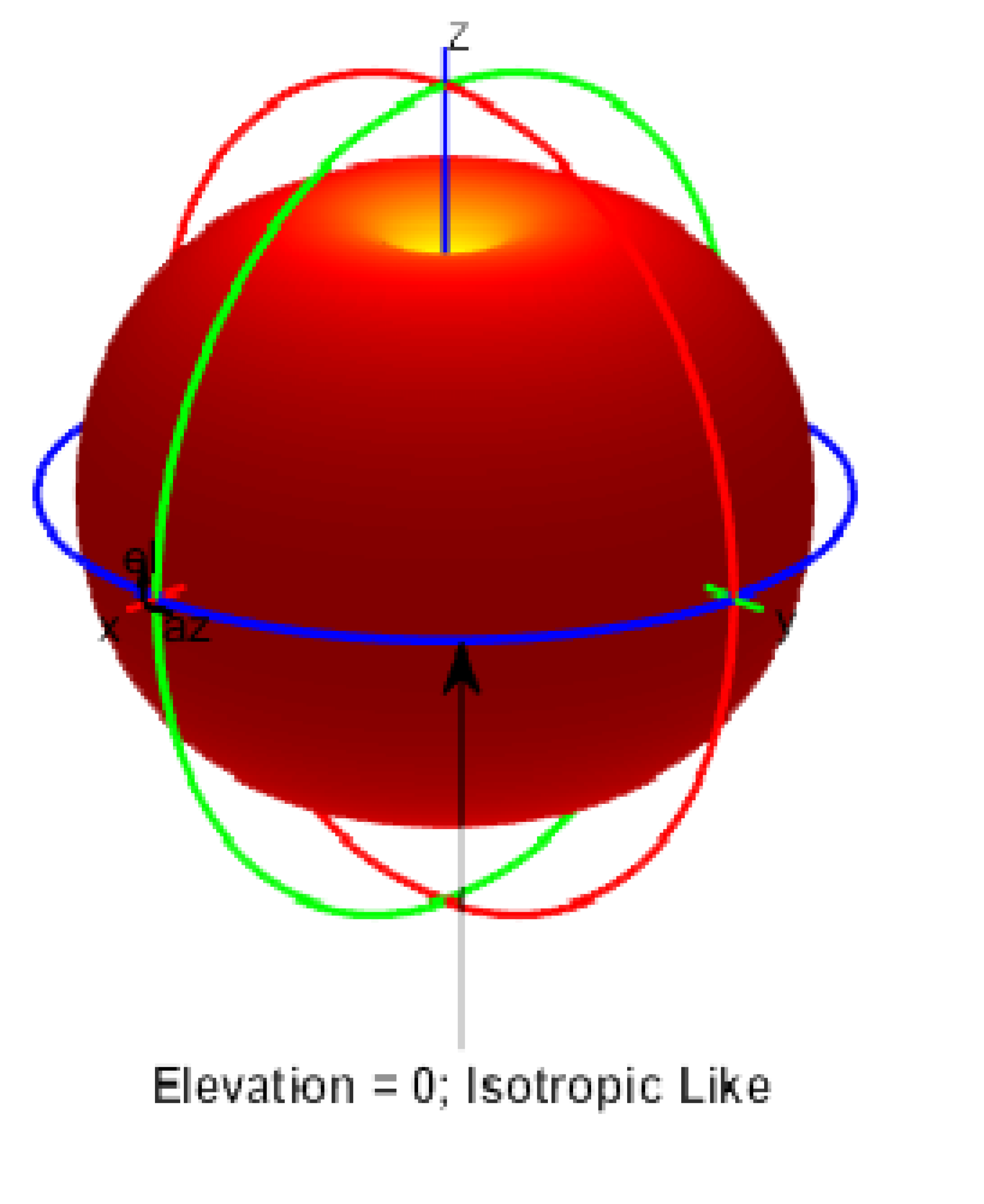
Antenna gain is measured in decibels, which is a ratio between two values. The gain of a specific antenna is compared to the gain of an isotropic antenna. An isotropic antenna is a theoretical antenna with a uniform three-dimensional radiation pattern (similar to a light bulb with no reflector). dBi is used to compare the power level of a given antenna to the theoretical isotropic antenna. An isotropic antenna is said to have a power rating of 0 dB, meaning that it has zero gain/loss when compared to itself.
Unlike isotropic antennas, dipole antennas are real antennas. Dipole antennas have a different radiation pattern compared to isotropic antennas. The dipole radiation pattern is 360 degrees in the horizontal plane and 75 degrees in the vertical plane (assuming the dipole antennais standing vertically) and resembles a donut in shape. Because the beam is “slightly” concentrated, dipole antennas have a gain over isotropic antennas of 2.14 dB in the horizontal plane. Dipole antennas are said to have a gain of 2.14 dBi (in comparison to an isotropic antenna).
Some antennas are rated in comparison to dipole antennas. This is denoted by the suffix dBd. Hence, dipole antennas have a gain of 0 dBd (=2.14 dBi).
Note that the majority of documentation refers to dipole antennas as having a gain of 2.2 dBi. Theactual figure is 2.14 dBi, but is often rounded up.
Types of Antennas
Interline offers several different styles of antennas for use with access points and bridges in both 0.8-6.5-GHz products. Every antenna offered for sale has been ETSI-approved. Each type of antenna will offer different coverage capabilities. As the gain ofan antenna increases, there is some tradeoff to its coverage area. Usually high-gain antennas offer longer coverage distances, but only in a certain direction. The radiation patterns below will help to show the coverage areas of the styles of antennas that interline offers: omnidirectional, Sectors, and patch antennas.
Omnidirectional Antennas
An omnidirectional antenna is designed to provide a 360-degree radiation pattern. This type of antenna is used when coverage inall directions from the antenna is required.
Figure 1. Omnidirectional antenna

Directional Antennas
Directional antennas come in many different styles and shapes. An antenna does not offer any added power to the signal; it simply redirects the energy it receives from the transmitter. By redirecting this energy, it has the effect of providing more energy in one direction, and less energy in all other directions. As the gain of a directional antenna increases, the angle of radiation usually decreases, providing a greater coverage distance, but with a reduced coverage angle. Directional antennas include patch antennas (Figure 2), and parabolic dishes. Parabolic dishes have a very narrow RF energy path, and the installer must be accurate in aiming these types of antennas these at each other.
Figure 2. Directional Patch Antenna

MIMO Antenna Systems
MIMO antenna systems are used to overcome a phenomenon known as multipath distortion or multipath interference. A MIMO antenna system uses two or more identical antennas, located a small distance apart, to provide coverage to the same physical area.
Multipath Distortion
Multipath interference occurs when an RF signal has more than one path between a receiver and a transmitter. This occurs in sites that have a large amount of metallic or other RF reflective surfaces.
Just as light and sound bounce off of objects, so does RF. This means there can be more than one path that RF takes when going from a transmit (TX) and receive (RX) antenna. These multiple signals combine in the RX antenna and receiver to cause distortion of the signal.
Multipath interference can cause the RF energy of an antenna to be very high, but the data wouldbe unrecoverable. Changing the type of antenna and location of the antenna or use MIMO access point can eliminate multipath distortion (Figure3).
Figure 3. Multipath

MIMO antennas can bring a number of potential benefits to mobile radio systems, including more reliable operation in poor signal conditions, greater spectral efficiency (and hence overall system capacity) and increased data rates for individual users. However, MIMO is a complex technology, with a number of variations on its basic principle.
- Spatial diversity exploits the independent fading of different signal paths between the various transmit and receive antennas to improve the reliability of a communication link. The same signal stream is transmitted from each antenna but with different coding applied, which enables the receiver to benefit from the diversity of the received signals. This technique is particularly useful for system control channels and for robust operation in poor signal conditions, such as near the edge of cells.
- Spatial multiplexing takes advantage of multipath propagation to create a number of independent transmission channels between the transmitter and receiver, which enables two or more different signal streams to be transmitted simultaneously. By applying suitable coding and signal processing these can be extracted independently at the receiver. This technique can be used to increase the throughput available to an individual user or to multiplex data from different users (commonly referred to as multi-user MIMO). The maximum number of multiplex channels that can be supported corresponds to the smaller of the number of antennas on the transmitter and receiver. For example, the MIMO arrangement shown above could provide two independent transmission channels if the radio conditions were suitable. This could be used to double the data rate available to a user or to carry two independent data streams.
- Closed loop feedback and precoding enables a transmitter to take advantage of information about the transmission channel, provided by the receiver. If feedback is available, the transmitter can modify its coding of the transmitted signals to take account of the prevailing channel characteristics, to simplify the signal processing required at the receiver and enable potentially greater performance gains.
The effectiveness of MIMO in a real network depends on a number of factors, including antenna separation on the transmitting and receiving devices, the level of scattering and multipath propagation in the radio path, the signal-to-noise ratio of received signals, and the speed of the mobile terminal. MIMO is at its most effective when there is significant multipath propagation, such as an urban environment where signals are scattered by buildings and other objects. In an open, rural location, where there is a strong line-of-sight transmission path between the transmitter and receiver, MIMO is less useful.
Different MIMO operating modes suit different circumstances. For example, closed loop operation works well with a terminal that is relatively static with high signal strength. However, its performance will be poor with a mobile terminal that is moving rapidly and experiencing low signal strength, because of delays and inaccuracies in providing channel feedback to the transmitter. In such cases it is preferable to use a simpler form of MIMO.
Wireless LAN Design
Before the physical environment is examined, it is critical to identify the mobility of the application, the means for coverage, and system redundancy. An application such as point-to-point, which connects two or more stationary users, may be best served by a directional antenna, while mobile userswill generally require a number of omnidirectional micro cells. These individual micro cells can be linked together through the wired LAN infrastructure or by using the wireless repeater functionality built into any access point that supports this function.
The Physical Environment
After mobility issues are resolved, the physical environment must be examined. While the area of coverage is the most important factor for antenna selection, it is not the sole decision criterion. Building construction, ceiling height, internal obstructions, available mounting locations, andthe customer’s aesthetic desires also must be considered.
Cement and steel construction have different radio propagation characteristics. Internal obstructions such as product inventory and racking in warehousing environments are factors. In outdoor environments, many objects can affectantenna patterns, including trees, vehicles, and buildings, to name a few.
Building Construction
The density of the materials used in a building's construction determines the number of walls the RF signal can pass through and still maintain adequate coverage. Following are a few examples. The actual effect on the RF must be tested at the site, and therefore a site survey is recommended.
Paper and vinyl walls have very little effect on signal penetration. Solid walls and floors and precastconcrete walls can limit signal penetration to oneor two walls without degrading coverage. This may vary widely based on any steel reinforcing within the concrete. Concrete and concrete block walls may limit signal penetration to three or four walls. Wood or drywall typically allow for adequate penetration through five or six walls. A thick metal wall reflects signals, resulting in poor penetration. Steel-reinforced concrete flooringwill restrict coverage between floors to perhaps one or two floors.
Recommendations for some common installation environments are outlined below:
● Warehousing/manufacturing: In most cases, these installations require a large coverage area. Experience has shown that an omnidirectional antenna mounted at 6 to 7 meters typically provides the best overall coverage. Of course, this also depends upon theheight of the racking, material on the rack, and ability to locate the antenna at this height. Mounting the antenna higher will sometimes actually reduce coverage, as the angle of radiation from the antenna is more outward than down. The antenna should beplaced in the center of the desired coverage cell and in an open area for best performance. In cases where the radio unit will be located against a wall, a directional antenna such as a patch or Yagi can be usedfor better penetration of the area. The coverage angle of the antenna will affect the coverage area.
● Small office/small retail store: The standard dipole may provide adequate coverage in these areas depending on the location of the radio device. However, in a back corner office a patch antenna may provide better coverage. It can be mounted to the wall above most obstructions for best performance. Coverage of this type antenna depends on the surrounding environment.
● Enterprise/large retail store: In most cases, these installations require a large coverage area. Experience has shown that omnidirectional antennas mounted just below the ceiling girders or just below the drop ceiling typically provide the best coverage (this will vary with stocking, type of material, and building construction). The antenna should be placed in the center of the desired coverage cell and in an open area for best performance. In cases where the radio unit will be located in a corner, or at one end of the building, a directional antenna suchas a patch or Yagican be used for better penetration of the area.
Also, for areas that are long and narrow - such as long rows of racking - a directional antennaat one end may provide better coverage. The radiation angle of the antennas will also affect the coverage area.
● Point-to-point: When connecting two points together (such as a wireless bridge), the distance, obstructions, and antenna location must be considered. If the antennas can be mounted indoors and the distance is very short (several hundred feet), the Logis mini or Horizon 7dBi omnidirectional antenna may be used. An alternative is to use two patch antennas. For very long distances (800 m. or more), directional high-gainantennas must beused. These antennas should be installed as high as possible, and above obstructions such as trees, buildings, and so on; andif directional antennas are used, they must be aligned so that their main radiated power lobes are directed at each other. With a line-of-site configuration, distances of up to 40 at 2.4 GHz and 20 kilometers at 5 GHz can be reached using parabolic dish antennas, if a clear line-of-site ismaintained. With the use of directional antennas, fewer interference possibilities exist and there is less possibility of causing interference to anyone else.
● Point-to-multipoint bridge: In this case (in which a single point is communicating to several remote points), the use of an omnidirectional antenna at the main communication point must be considered. The remote sites can use a directional antenna thatisdirected at the main point antenna.
As stated above, cabling introduces losses into the system, negating some of the gain an antenna introduces and reducing range of the RF coverage.
Interconnect Cable
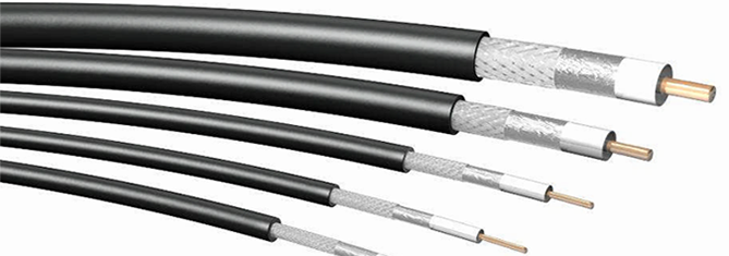
Low-Loss/Ultra-Low-Loss Cable
Interline offers two styles of cables for use with the 2.4-GHz and 5-GHz product lines. These cables provide a much lower loss factor than standard interconnect cable, and they can be used when the antenna must be placed at any distance from the radio device. While these are low-loss cables, they should still be kept to a minimum length.
There are two types of cable supplied by Interline for mounting the antenna away from the radio unit. The 10- and 15-meters cables are RF10 type cable, while the 1- and 10-meters cables are RF-240 type cables. All four lengths are supplied with one Nmale, Nfemale, RP-SMA, RP-TNC jack connector attached. This allows for connection to the radio unit and to the interconnect cable supplied on the antennas.
To ensure compatibility, use antennas and cabling from Interline.
Mounting Hardware
Each antenna requires some type of mounting
Mast mount antennas are designed to mount to a variety of mast diameters and each comes with mounting hardware for attachment. Patch and omnidirectional antennas are designed to mount flat against a wall or ceiling.
Lightning Arrestors
When using outdoor antenna installations, it is always possible that an antenna will suffer damagefrom potential charges developing on the antennaand cable, or surges induced from nearby lightning strikes. The interline lightning arrestor is designed to protect DC- to 7.0- GHz radio equipment from static electricity and lightning-induced surges that travelon coaxial transmission lines. Both systems need to be properly grounded as identified in the hardware installation manuals of the products. These protection mechanisms will not prevent damage in the event of a direct lightning hit.
- Log in to post comments
