




RF Connectors and Cable Assemblies
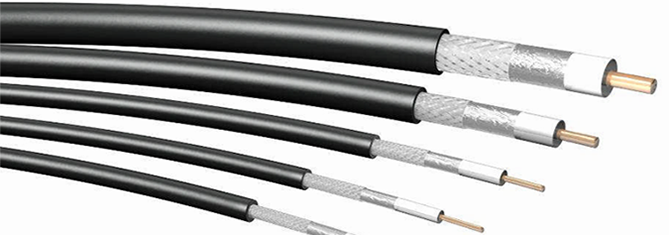
Interline manufactures professional RF cable assemblies for antenna systems, radio communication equipment and wireless installations. We use different cable types depending on the application, frequency range, required attenuation, mechanical durability and installation environment.
Our cable assemblies can be prepared with measurement documentation, including VSWR and insertion loss data. This helps installers choose the correct cable length, connector type and antenna configuration for reliable long-term operation.
Design your antenna system with cable loss in mind
In professional radio communication systems, cable attenuation between the radio device and the antenna should be kept as low as possible. As a general rule, the total cable loss should not exceed approximately 2 dB whenever the installation conditions allow it.
Correct cable selection becomes especially important at higher frequencies such as 5 GHz, Wi-Fi 6E and microwave radio systems, where cable attenuation can significantly reduce overall system performance.
We are preparing a universal RF cable attenuation calculator for different cable types. It will help compare cable losses for various lengths and frequencies.
Outdoor and indoor RF connectors
For outdoor antenna installations, connectors should provide proper sealing and mechanical reliability. Clamp-type connectors with silicone gaskets are recommended for outdoor use because they protect the connection against moisture and water ingress.
For indoor installations, standard crimp connectors may be sufficient when the environment is dry and the cable is not exposed to water, condensation or major mechanical stress.
Interline offers various RF connector types, including N male, N female, SMA, RP-SMA, RP-TNC, TNC, FME and U.FL / IPX micro coax connectors.
Photos of coaxial cable connectors
The reference chart below helps identify common RF connector types used in wireless devices, routers, antennas and radio communication equipment.

SMA vs RP-SMA connector comparison
SMA and RP-SMA connectors are often confused because they use the same thread dimensions but different pin configurations. Incorrect connector selection is one of the most common problems during antenna installation and wireless device integration.
The illustration below shows the mechanical differences between SMA and RP-SMA connector types.


| Frequency/częstotliwość (MHz) | BELDEN RG174/U 7805R (1m) | RF10 H-1000 (1m) | MRC240/RF240 (1m) | RF5 (1m) | H-155 |
|---|---|---|---|---|---|
| 900 | 0,66 | 0,12 | 0,25 | 0,29 | 0,29 |
| 1800 | 0,97 | 0,18 | 0,36 | 0,42 | 0,42 |
| 2500 | 1,16 | 0,22 | 0,43 | 0,5 | 0,5 |
| 5200 | 1,91 | 0,34 | 0,64 | n/a | n/a |
| 5800 | 1,94 | 0,36 | 0,67 | n/a | n/a |
| Outer diameter/ średnica zewnętrzna (mm) | 2,8 | 10,3 | 6,1 | 5,4 | 5,4 |
| Min. Bending Radius/min. promień gięcia (mm) | |||||
| Without load / bez obciążenia | 14 | 55 | 30,5 | 27 | 27 |
| With load / z obciążeniem | 28 | 110 | 61 | 54 | 54 |
| Minimum | Recommended | |
|---|---|---|
| N | 0.7 N-m | 1 N-m |
| SMA / RP-SMA | 0.34 N-m | 0.56 N-m |
| RP-TNC | 0.68 N-m | 0.69 N-m |