PANEL 8 HELIUM SL
Product code: 
IP-G08-F8688-SL


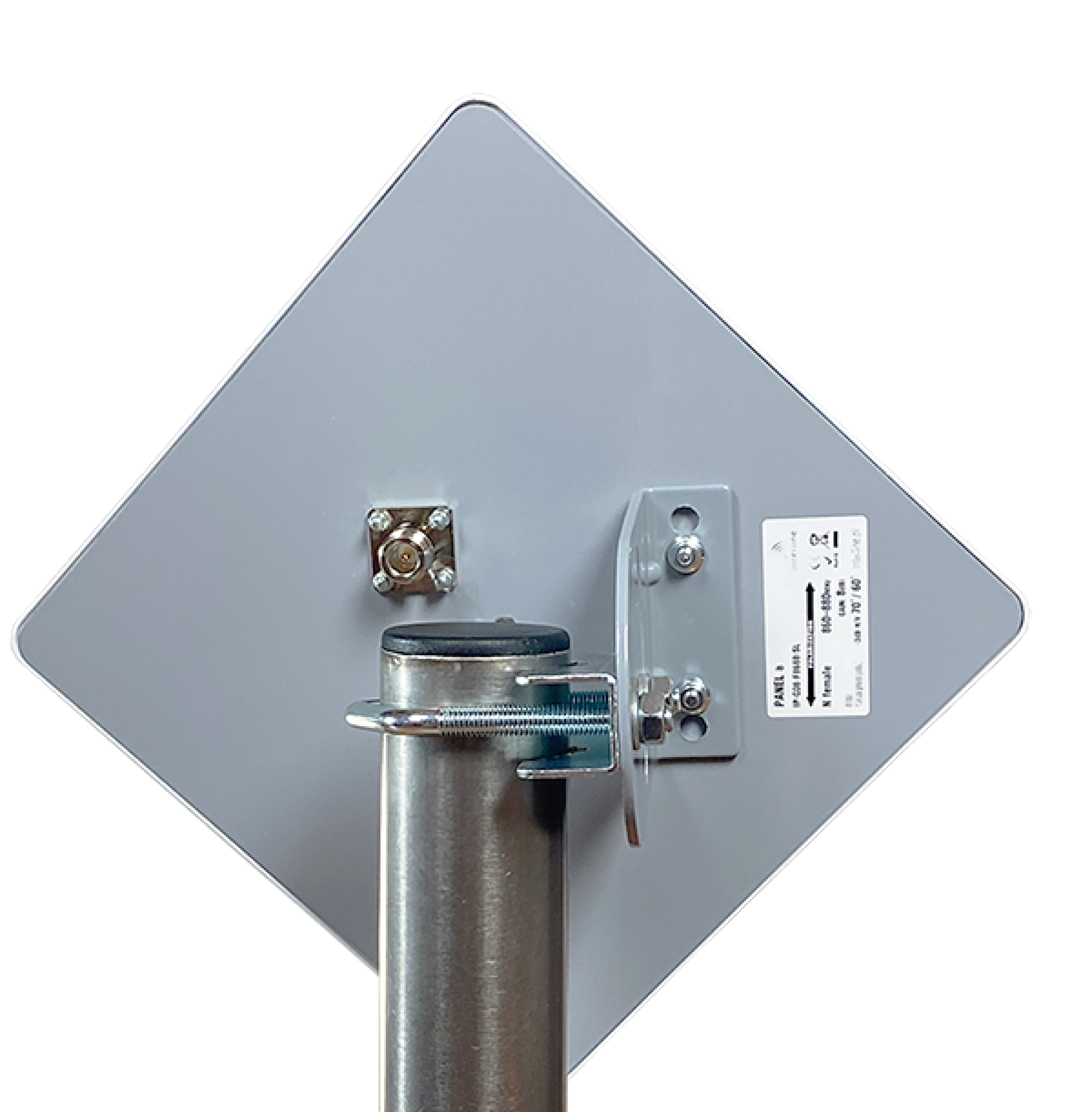
8.0 DBI TUNED DIRECTIONAL ANTENNA (EU 868)


Directional antennas pick up less noise compared to omnidirectional antennas. This increases the SNR (signal to noise) parameter, and extends the effective range.


The 8.0dBi Optimised Helium Antenna offers +7% forward Power Transmission compared to alternative non optimised VSWR Antenna designs.

  • Results in higher coverage and Increased HNT $ revenue.

interline has launched it’s newest addition to our market leading Ultra High Performance Optimised and Tuned Lora Frequency Band Antenna series

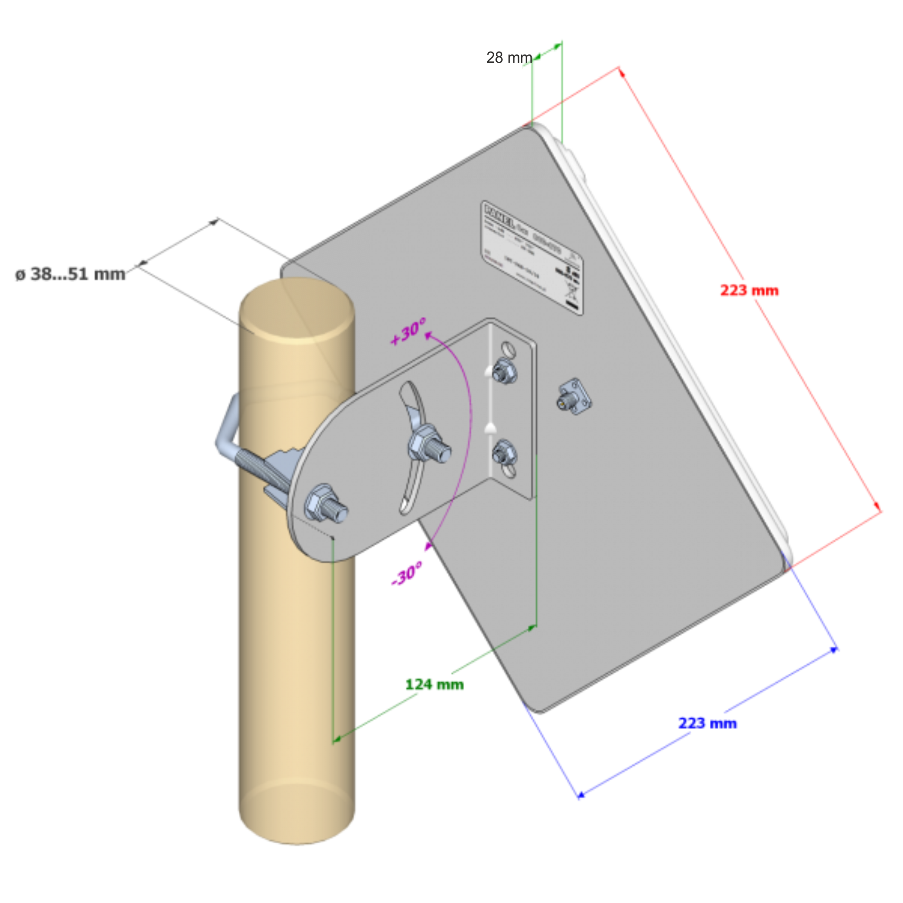
The unique 8.0 dBi Tuned Directional Antenna is both directional and has the additional significant advantage that it can be tilted or moved in the Azimuth direction – unlike all other Omni Directional Antennas.

Omni directional Antennas radiate 360 degrees – this unique flat panel Antenna design is radically different in that it takes all of the radiated energy which usually would be transmitted behind and to the side of the Antenna and focuses all of this RF energy into the forward direction only –

in one very wide and high beam – typically 70 degrees in Azimuth and Elevation.


Typical applications:

  • Where it’s desired to steer /direct the Radiated beam into a large or difficult to reach target area. This is achieved by utilising the unique feature of this Antenna design of being able to tilt or move in the Antenna utilising it’s tillable and rotatable Antenna Mount (supplied) to focus the      large beam exactly in the direction required.
  • Ideal for mounting on high up Balconies or Tower Blocks where Antennas are blocked from radiating in the rearwards direction.
  • Installations located on the coast where transmission to the antenna rear is not required/desired.
  • Installations located immediately in front of large hills or building where rear radiation is blocked and therefore not required.
  • The flat panel sector Antenna is small ,lightweight and unobtrusive and white in Colour.
SLANT POLARIZED ANTENNA
 
Designed for systems- HELIUM  the People's network , IoT M2M ( Machine to Machine )  Lora, Sigfox, XBee, RFID. Z-WAVE and etc.
 
 The non-line-of-sight (NLOS) scenario is far more common and presents challenges for all types of wireless systems, especially those in which one end of the link is mobile. When there is no clear line of sight, degradation will result from reflections, refraction, diffraction, scattering and atmospheric absorption. The multiple signals created by these factors will then arrive at the receiving antenna at different times, from different paths and with different strengths. The result will be a reduced link margin and decreased throughput, and in a worst-case scenario, make communications impossible.
 

SLANT POLARIZED

Antennas can mitigate some of these problems using various techniques, the most common being polarization diversity. It is used in all types of wireless applications including cellular and the fixed wireless access (FWA) systems used in rural areas to deliver residential broadband service. Polarization diversity is basically the use of antenna systems that radiate signals in more than one polarization, such as horizontal and vertical.


Figure 4. At left is horizontal/vertical polarization with respect to the horizon, and at right the depiction is polarized ±45 degrees. The electric and magnetic fields are shown in blue and brown.

Dual horizontal and vertical polarization has been used for many years in wireless systems, but has mostly been replaced by skewed polarization (see Figure 4). In the Helium Panel 8, after selecting the horizontal or vertical polarization (it depends on how the antenna holder is attached), the antenna radiator radiates at an angle (+45 degrees and -45 degrees). We recommend setting the antenna in vertical polarization which is the most common use case.

Slant Configuration Benefits

Various studies have determined that this ±45-degree slant configuration can provide benefits that H and V configurations do not. Dual-slant polarization is midway between horizontal and vertical and signals from the two antennas combine into a linearly polarized transmitted wave, therefore reception can be improved over pure H or V. Slant polarization has also proven its ability to provide signal improvement through foliage as well as in NLOS conditions.

In addition, slant polarization can minimize some of the effects of signal variability, reduce interference between antennas and increase the signal-to-noise ratio (SNR). These benefits apply to any operating scenario and especially to urban and other environments where signals are scattered, reducing their strength in a given location.

In antenna design, the horizontal and vertical polarizations often have unequal patterns and gain due to the physical asymmetries of the antenna’s construction. This can be readily observed in each polarization’s patterns, in which the beam width of the vertical polarization is narrower than the horizontal beam width. As a result, the gain of the vertical signal is weaker near the sector edges, which causes a chain imbalance. In a ±45-degree slant configuration, there are no physical asymmetries in the antenna and each polarization has nearly identical patterns that equalize the signal strength of both polarizations.

Withstanding Fading

Slant polarization appears to be able to withstand the effects of fading caused by reflections better than horizontal/vertical polarization, and some sources cite its ability to reduce interference where there are many simultaneous emitters. Finally, received signals typically appear at the receiving end more vertically than horizontally polarized, creating an unequal relationship, as vertical polarization often delivers a stronger signal than its horizontal counterpart at the receive location. Slant polarization can minimize this issue by equalizing the signal levels from both orientations.

Although slant polarization should theoretically cause a 3-dB (half-power) reduction in link budget caused by polarization mismatch, multipath propagation has the effect of restoring it because polarization is no longer purely horizontal/vertical and at a ±45-degree slant. The result is typically only about a 1-dB reduction in link budget.


SNR - Signal to noise ratio

Panel antennas, being directional antennas, with the same gain, always have a higher signal-to-noise ratio compared to omnidirectional antennas.


PANEL 868 MHz is carefully designed and construction directional antenna working in the unlicensed in Europe -  863-870MHz band.
Typical applications are monitoring and digital transmission of small amounts of data (up to 50 kbps)

  • RFID 
  • Tunnels, underground passages
  • Energy (wind, solar panels),
  • Intelligence Home
  • Internet of Things
  • Irrigation,
  • Telemetry,
  • RF sensor networks
  • tracking people and objects
  • geolocation,
  • safety of workers.
  • Covering a strictly defined area.
  •  

The antenna housing is grounded, which protects it against electrostatic discharge

 (electric charges appearing on the antenna are discharged to the earthing system)


For proper operation, the mast on which the antenna is mounted must be grounded to the existing lightning protection system.


Despite the lack of a device lightning protection, antenna mast or the supporting structure of the antenna must be earthed.


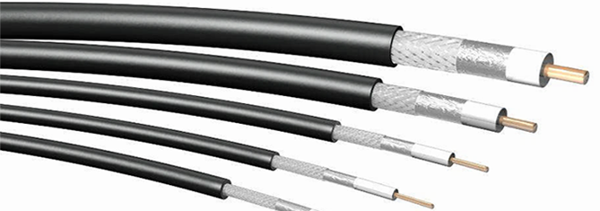
 The ground wire should form the shortest and direct path to the earth electrode Outer sheaths of coaxial cables outgoing antenna should be connected to the antenna mast or to the cablewith an equipotential bonding conductor ocross-section not less than 8 mm2 Cu.


For additional safety, install a gas lightning arrester. The assembly instructions are HERE.

Key benefits

  1. Solid casing
  2. Powder painted backplate
  3. Radiators Protection ( with a special varnish )

Features

  1. Low level of side lobes
  2. Adjustable mounting
  3. Sector coverage
  4. Sector optimalization
warranty:

compliance

Last updated date

05/11/2022 - 12:28
Loading 3D views:

electrical

Frequency band(s)
  1. 860-880
Frequency (min)
860MHz
Frequency (max)
880MHz
Gain
  1. 8dBi
VSWR (max)
1.50:1
Polarization
Horizontal and Vertical
Half Power Beam Width (-3dB) - horizontal
  1. 70°
Half Power Beam Width (-3dB) - vertical
  1. 60°
FBR (Front/Back Ratio)
>25dB
XPD (Cross Polarization Discrimination)
>3dB
Max Composite Power
50W
DC Ground
yes
Impedance
50Ω

mechanical

Connector
N female
Mounting Diameter
ø 38…51mm
Dimensions (excl. mount)
223x223x28
Weight (incl. mount)
0.65kg

enviromental

Enviroment
Outdoor
Windload
160km/h
IP Rating
IP67
Temperature
-40°C ... 80°C

Click button to show plot